
Introduction
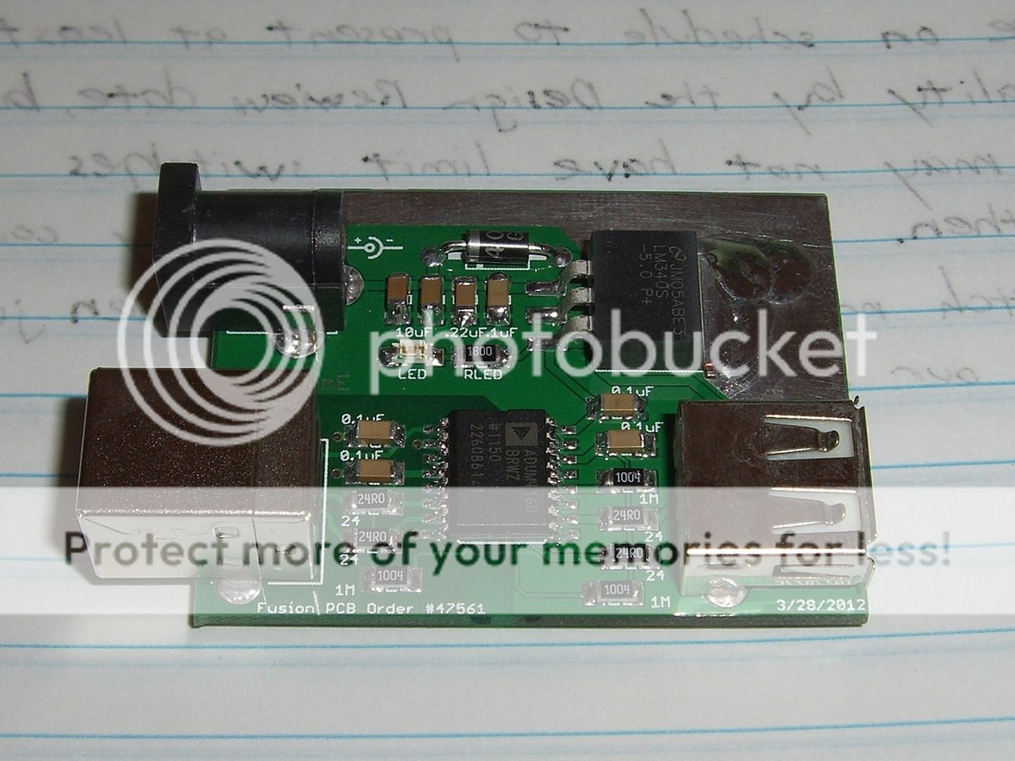
This is a pretty short and simple project – as you might be able to guess from the title it’s essentially an adaption of the USB Isolator from Circuits@Home except with the whole switching power supply section cut out and a LM340-5.0 based linear regulator section spliced in there instead. The pin header to switch between low/full speed USB mode is eliminated as well and this version is locked to full speed operation. I've also added in a little power LED to let you know things are working. Full credit goes to Circuits@Home for an overall excellent original design.
I intend for this thing to be used as a sort of isolator dongle for USB DACs and other devices that want cleaner 5V power than typical switching regulators or USB bus power offer. The assembly is kept very low profile with the use of mostly SMD parts.
Parts List
I won’t go into too much detail here as it is a relatively straightforward build for experienced DIYers and I encourage you to go out and find your own parts rather than just copying and pasting the part numbers I've written down below.
I won’t go into too much detail here as it is a relatively straightforward build for experienced DIYers and I encourage you to go out and find your own parts rather than just copying and pasting the part numbers I've written down below.
Part
|
Qty
|
Notes
|
1
|
Heart of this board as you can probably guess. You can buy them from Circuits@Home or Digikey.
| |
1
|
5V fixed TO-263 form factor VREG. Ground plane of the board serves as a heatsink for this IC.
Mouser Part #926-LM340S-5.0/NOPB or 926-LM340SX-5.0/NOPB
| |
1N4001/1N4002 Diode
|
1
|
Protection diode for VREG - you can find these guys pretty much anywhere.
I have a bunch that I got for cheap from thaishopetc
Mouser Part #625-1N4002E-E3/54 should work
|
24Ω 1% tolerance 1206 SMD Resistor
|
4
|
I'm using Vishay CRCW120624R0FKEA from Mouser
|
1MΩ 1206 SMD Resistor
|
3
|
I'm using Vishay CRCW12061M00FKEA parts from Mouser
|
MLCC 0.1uF X7R 1206 SMD Capacitor
|
5
|
Power supply bypass capacitors
I'm using Vishay VJ1206Y104KXAMC parts from Mouser
|
MLCC 0.22uF X7R 1206 SMD Capacitor
|
1
|
Required bypass cap for the VREG since it's located far away from the power supply filter caps
I'm using Vishay VJ1206Y224KXATW1BC parts from Mouser
|
MLCC 10uF X7R 1206 SMD Capacitor
|
2
|
Optional additional bypass for the VREG; I recommend using at least the 0.1uF and 0.22uF regulator input bypass caps in but the 10uF ones aren't really necessary
I'm using Taiyo Yuden TMK316B7106KL-TD parts from Mouser
|
PWRLED - 1206 SMD LED
(optional) |
1
|
Pretty much any 1206 SMD LED will do; I have a bunch laying around from Sky-Electronic Mart
Something like Mouser Part #859-LTST-C230TBKT should work. If you don't feel the need for a power indicator you can just leave this out, it'll save you a bit of power I suppose since it does take ~20mA) |
RLED - 1206 SMD Resistor
(optional) |
1
|
Value depends on the specs of the LED you choose (LED Calculator Link) and how bright you want it to be
I'm using 180Ω Vishay CRCW1206180RFKEA parts bought from Mouser with my cheap LEDs from Sky-Macau that have a FV of 2.2V and FC of 20mA.
|
Wall Wart Adapter (unregulated DC)(center tip positive)
|
1
|
I suggest the Triad Magnetics WDU75-800 which can be bought from Mouser.
If you decide to browse eBay find something with the following: -isolated from earth ground (i.e. has a transformer inside it) -2.1mm ID / 5.5mm OD plug; center tip positive! -preferably between 7.5V-9V to minimize power dissipation -output current capability 500mA or more |
2.1mm/5.5mm DC Power Jack, Right Angle
|
1
| |
USB “A” type connector, right angle through hole PCB mount.
|
1
| |
USB “B” type connector, right angle through hole PCB mount.
|
1
|
Rev.1 (Prototype)


The above images are of my first revision prototype boards; there have been quite a few changes to the board since then.
I tested this unit for quite some time and it worked fine but got incredibly hot. I never actually ran into thermal shutdown but the whole board and connectors were getting hot to the touch - part of the reason for this heat is because I was using a 12V power supply; the higher the input voltage the more power the linear regulator IC has to dissipate, which is why I recommend a 7.5Vdc wall wart in the parts list. (typical dropout voltage of the LM340 is 2V)
With only a small exposed ground plane as a heatsink, a SOT-223 voltage regulator IC can only dissipate about 1W of power. This means that (Vregin - Vregout)*(Load Current) < 1W. So if you use a 12V adapter to power this thing you would get a maximum load current of only about 150mA which not really enough to drive more power hungry USB devices such as DAC/headphone amp combos.
The TO-263 part in my newer revision boards should be able to comfortably handle 2W of power which would allow for 300mA of continuous current with a 12V adapter and 500mA with a 9V adapter. I've exposed a fairly large portion of the PCB as a heatsink for the regulator IC since we want this thing to stay as cool as possible for long term reliability and load regulation performance.
Rev.2 (Current)
Changes from Rev.1:
-Eliminated pin headers; now locked to full-speed operation
-TO-263 5V regulator and large exposed ground plane area for additional power handling capabilities
Project Materials
I used to have a bunch of extra PCBs and parts laying around but I sold them in bulk to another guy who was interested in the project. The PCB is fairly small and doesn't cost too much to have made at OSH Park.
Assembly
Basic assembly procedures are more or less the same as with Circuits@Home’s original design.
Those experienced with soldering should have no issues with the assembly except for potentially with soldering of the main USB isolator chip; I find the ADuM4160 IC is actually large enough for me to simply align with my left hand while soldering it with my right. Be particularly careful of solder bridges between the pins of this IC! All of the SMD resistors and capacitors are 1206 which is fairly large within the SMD realm. I was able to put this whole thing together in about an hour; most people should have no trouble completing this project in under two hours.

1. Solder on the regulator IC and its input capacitors - I'd start with the smaller legs of the VREG IC; it's actually quite difficult to get the tab down as its being heatsinked so effectively by the board. You may need to use higher temps to get the tab soldered down.

2. Solder down some more of the surrounding components in whatever order you'd like. Once you have the pictured components soldered down, you should be able to plug in your DC adapter and see the LED light up. Use a DMM to test for 5V at the output of the regulator. (use the 0.1uF cap pads right below it)

3. Solder down the main isolator IC - be careful of solder bridges here. Start with one corner pin and spend some time getting things lined up correctly.

4. Solder surrounding caps/resistors and finally the USB jacks.
5. Clean with brush and lots of IPA.
6. Verify basic functionality with some sacrificial flash drive of yours. Copy a large .zip file over to it and use 7-zip or similar to check the archive for errors. I saw copy speeds of only ~800KBps so it may take a while.
Maximum Power Considerations
With the ~0.6 sq in exposed ground plan on each side of the board: (Vregin - Vregout)*(Load Current) < 2W for the TO-263 LM340-5.0 VREG
If you stick with the 7.5V adapter that I've recommend in the parts list, then you'll find that things will stay as cool as possible and you should be able to handle pretty much any USB device. A standard PC USB port can supply 500mA of continuous current so you'll be able to match this by using a 7.5V-9V adapter.
-If you only plan to use this USB isolator with fairly low-powered devices (<200mA current) then you should have no thermal issues whatsoever with any power adapter from 7.5V-12V.
-If you are going to be using this isolator with more a power hungry device such as a USB DAC (>300mA) I recommend going all out on the heatsinking as I've done here and sticking to power adapters in the 7.5V-9V range only.
-Do not use this isolator with any USB device that draws more than 500mA of current. I believe this is generally limited to a few devices that quick charge batteries over USB.
The ground plane should keep things cool enough for proper operation as long as your adapter is 7.5V-9V but the regulator IC will still be getting fairly toasty if you're driving heavy duty devices so extra heatsinking never hurts. Just make sure your heatsinks aren't shorting out any circuit elements. The VREG has a maximum junction temp of 125C and features internal thermal shutdown to protect itself so you are unlikely to destroy it even without extra heatsinking, but again it's always better to stay as cool as possible.
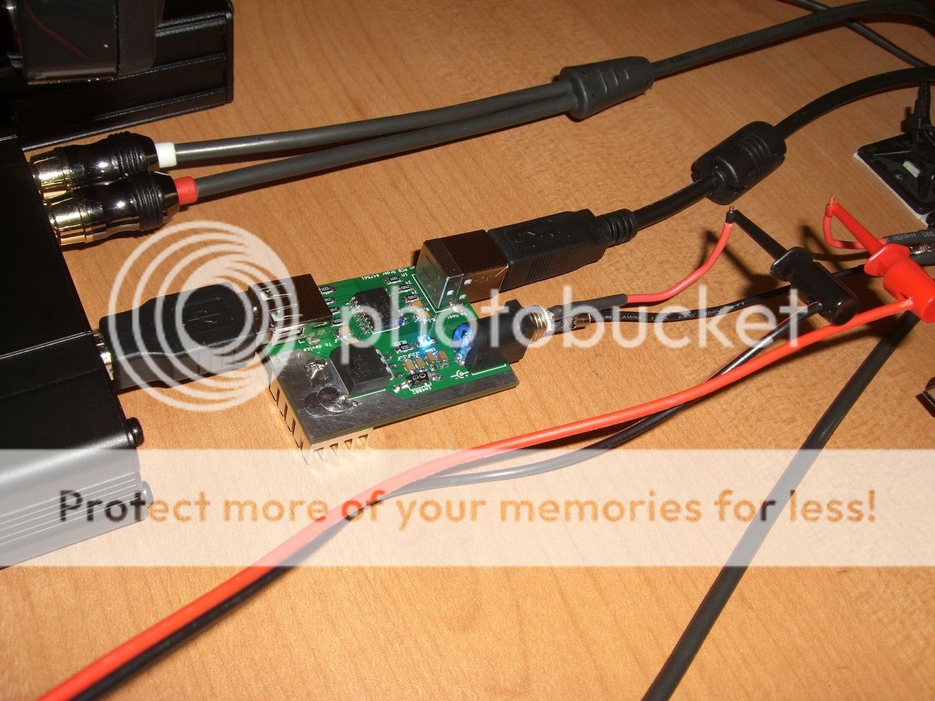
I used the following contraption to test the current consumption of several USB devices:

No devices connected: 18mA (idle power of the ADuM4160 and power LED current)
DPScope SE: 70mA
USB Flash Drive: 90mA
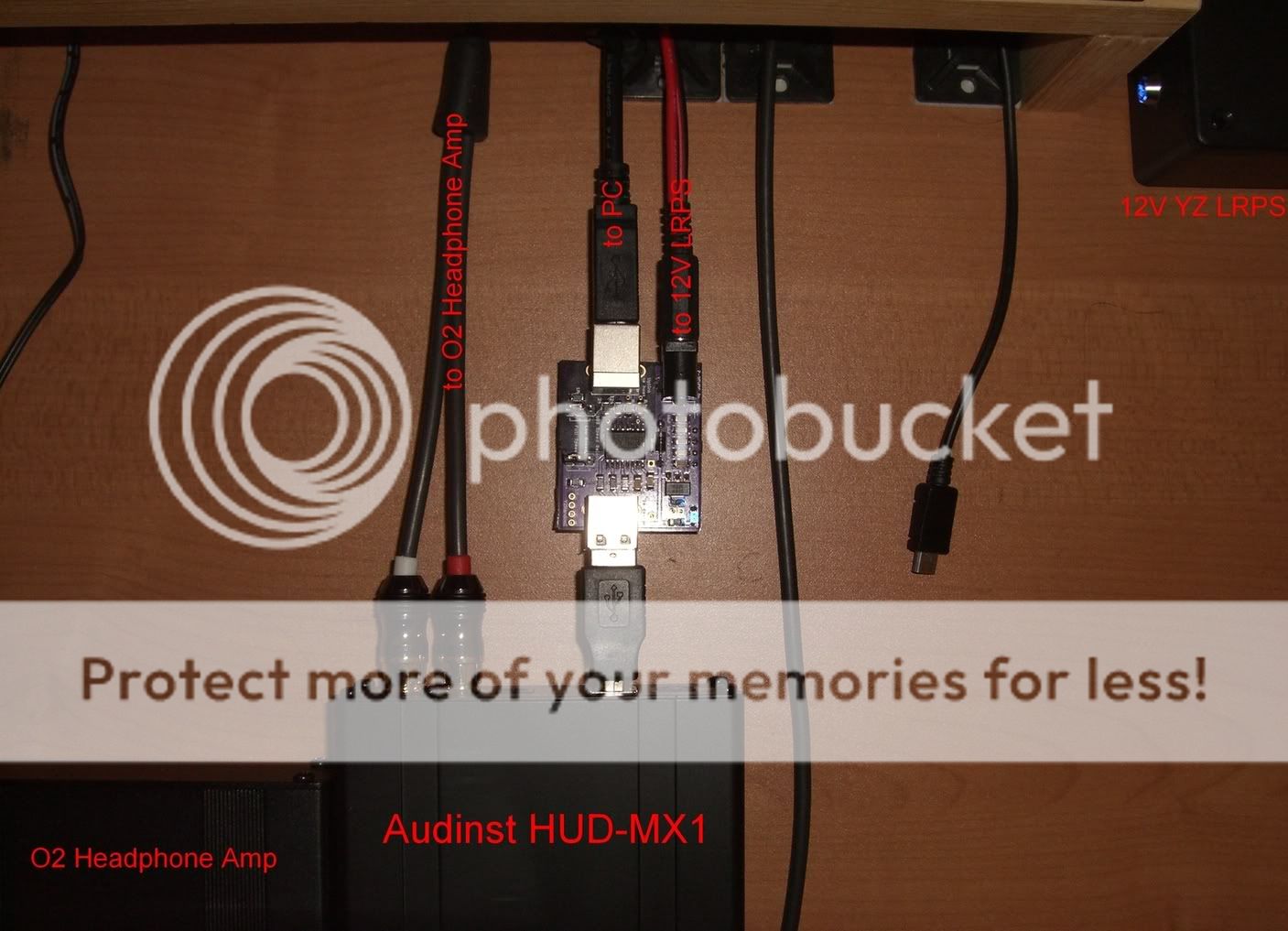
Audinst HUD-MX1 (USB power only): 340mA
Galaxy S 4G (charging): 500mA
I've been stress testing my isolator driving the Audinst HUD-MX1 (340mA) with a 7.5V power adapter (measured 9V when driving the Audinst) and only the bottom heatsink as pictured below. (~1.4W dissipated by regulator IC)
After 12 hours of continuous testing the above setup the highest temp I could measure with my IR gun was about 50C which isn't too bad.
When charging my Galaxy S 4G @ 500mA the 7.5V power adapter measured 8V and after several hours I still measured about 50C at highest with my IR gun. I probed around the exposed ground plane and surface of the regulator IC to find the highest temp. (~1.5W dissipated by regulator IC) Output voltage of the regulator IC measures a stable 5.08V under these conditions. (USB spec states you should stay within 4.45V–5.25V)
So far it seems like everything is working fairly reliably even under heavy loads.
Rev.3 (Future)
These are a few possible changes I would consider if I were to pursue a Rev.3:
-addition of miniature slide-action power switch
-remove 1N400x protection diode due to low risk of input short
-remove 1N400x protection diode due to low risk of input short
-integration of ACM3225 common-mode choke as per Analog Devices CN0160
-optimize layout per AD application guides and consider transition to 4-layer PCB
-optimize layout per AD application guides and consider transition to 4-layer PCB
-two holes for mounting 6-32 standoffs
Disclaimer: I won't take any responsibility for things getting blown up or otherwise destroyed. The project is open and should be considered unverified with only limited testing conducted by myself.
Sweet! Very nice work. I could use one of these inside my DIY Buffalo DAC.
ReplyDeleteA couple possibilities for Rev.3:
- option to use a mini-USB receptacle
- one or two holes for attaching standoffs (to mount in a large enclosure)
I have a fully assembled Rev.2 board up for sale on eBay if you're interested: http://www.ebay.com/itm/140742147734?ssPageName=STRK:MESELX:IT&_trksid=p3984.m1555.l2649
DeleteI don't expect it to sell for much as I'm mostly just looking for people to help me test it at this point.
As for your Rev.3 suggestions I could probably squeeze in 2-3 holes somewhere for mounting.
Were you thinking of mini-USB on the host or device side?
Thanks! Eagerly waiting for the board's arrival now.
DeleteThe mini-USB suggestion is for the host side. It's not really that important. Just that I have lots of spare mini-USB cables.
Will this operate at USB 2.0 speeds (the note on copying a file made me wonder)? If so, there may be interest in this device for folks that are using USB-powered software defined radios (google 'rtl2832u sdr'). If you have any more you're willing to unload at a similar price, let me know and I will test them with that application Thanks!
ReplyDeleteUnfortunately no - the ADuM4160 is limited to Full Speed 12Mbps so if you need High Speed 480Mbps you're out of luck.
DeleteIf you are still interested I have enough parts to construct one more unit (no power adapter supplied though like the previous listing) - it's always nice to have people testing with different applications.
I've been using this for a couple days now. Works very well.
ReplyDeleteI took some current draw readings with some different DACs just for fun.
AMB Gamma2 (with the y1 section omitted)--
USB mode, idle: 208mA
USB mode, active: 225mA
S/PDIF mode, idle: 199mA
S/PDIF mode, active: 221mA
any mode, self-powered: 17mA
Creative Xmod--
Idle: 82mA
Active: 83mA
Active with X-Fi mode: 87mA
Active with CMSS-3D: 89mA
Active with X-Fi + CMSS-3D: 93mA
(connecting to headphones didn't seem to affect the current draw)
GrubDAC--
Idle: 53mA
Active: 54mA
(connecting to an amp didn't seem to affect the current draw)
The isolator board got hot as expected for the Gamma2. But with the other two DACs it was just a little warm. Is there a recommended case that pairs with this? If not I'll probably try and mount it sideways into an Altoids tin. :)
I still have a couple other DACs to try pairing with this as time permits.
Thanks for the current measurements - it's nice to have some references for how much current typical USB DACs require. (evidently my Audinst HUD-MX1 is very power hungry)
DeleteAs for cases I didn't really have anything particularly in mind. I kinda thought about it during the design but I couldn't find anything that it would fit nicely into.
I prefer to just use mine enclosure-less as I have pictured so it takes up the least space possible but I figured that people would just tape it down inside Altoids tins or whatever as they see fit. Just make sure your Altoids tin isn't shorting out anything on the board.
Took a couple more measurements.
ReplyDeleteCreative X-Fi Go: 116mA - 118mA (depending on idle/active and loaded/unloaded).
iPod Touch 3rd Gen, charging: 428mA.
I also tried the isolator with my Teralink-X2 USB to SPDIF converter. I have the "module" version that includes it's own rectifier and linear regulator. I use this inside my Buffalo II DAC for USB input. Originally I was planning to either give the isolator board its own power supply, or tap a 5V source from the Teralink-X2 board to feed it. But unexpectedly (to me anyway), the isolator LED lit up when I connected it to the powered Teralink, even before I plugged in the isolator's wall wart. That result was probably obvious, but I guess I'm still a bit of a noob at this.
I also found that a 4-40 screw fits nicely through the board holes meant for the 2.1mm power jack. That is, use one of the holes for a standoff. So even with the rev2 board, it can be easily mounted in an enclosure if you wire the DC power in through an off-board panel mounted jack.